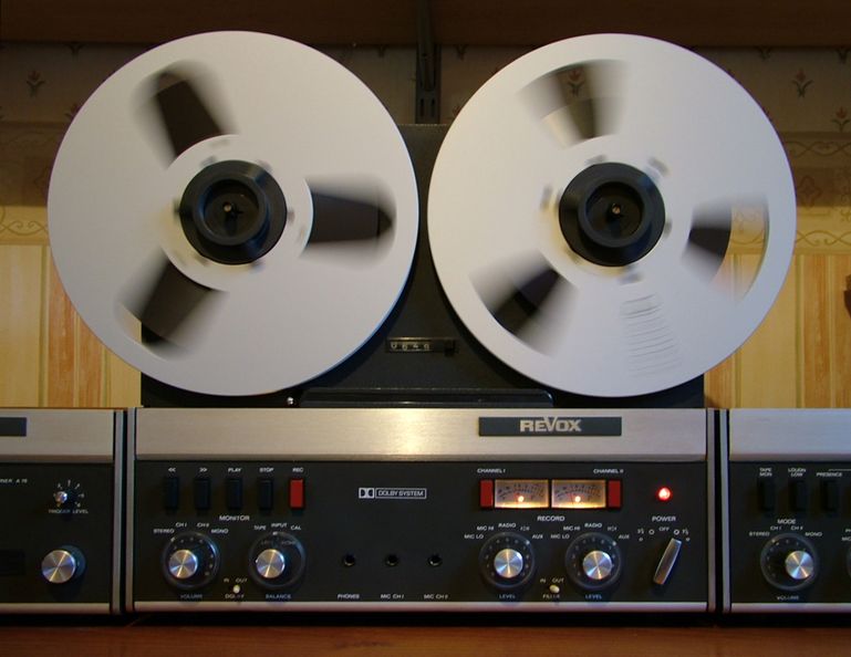
I've owned a 1973 vintage Revox A77 (a standard speed, 4 track, Mark 3 with Dolby B) since 1986, when I bought it for £300 from a musical instrument shop called "Tune Inn" in Hither Green (South London). That shop is still there and now has a web site: http://www.tuneinn.co.uk
I don't think (in retrospect) that this A77 was in very good condition - the heads were worn and the rotating tape guide made a fearful noise when rewinding tape. But I'd wanted a Revox A77 since I saw one at school. That must have been about 1970 and I was 11 years old. The quality of the thing was obvious, though, even at that age. So once I'd seen this one in the shop, I had to buy it!

I used it for recording off the radio on and off, but it never sounded as good as I hoped it would (not suprisingly). Eventually, in 1997, I had some money to spare and I saw an advertisement offering Revox servicing in the back of "HiFi News and Record Review". So - off it went for what I hoped would be a comprehensive renovation.
Unfortunately, that didn't turn out too well ... Everything started off fine - new heads were fitted and all the worn mechanical parts were replaced. Then there was silence for about 3 months ... I think the person doing the work had some sort of personal crisis. Eventually, I managed to get in touch with him, paid him and got the machine back. He'd done a lot of work on it, and mechanically it was now sound. But it still didn't sound all that good and there were definitely electrical problems (audible distortion on one channel and I strongly suspected that it hadn't been set up properly - or at all).
Due to pressure of work, not much happened until 2003, when I fixed the distortion problem (by replacing one of the transistors in the input amplifier). It now sounded a lot better - but still not as good as I thought it should.
Over the years, I'd built up a collection of Hewlett-Packard and Tektronix test gear (thanks mostly to E-Bay) and, having all the necessary equipment to hand, I finally made some time to sort the A77 out once and for all. Or so I hoped ... (I was also prompted by the arrival of audible distortion on the channel I hadn't fixed before!)
"Sorting it out" turned out to be a rather long winded process. One issue was that the Dolby specific aspects are not very fully described anywhere in the three manuals I have to hand. I know that the person doing the renovation in 1997 got really despondent about the Dolby side of things.
These are the manuals I got hold of:
And here is what I did (it goes on a bit - but the Dolby B specific parts might actually be useful to someone!):
- Clean the tape path and heads thoroughly with Isopropyl Alcohol (IPA) and Q-Tips.
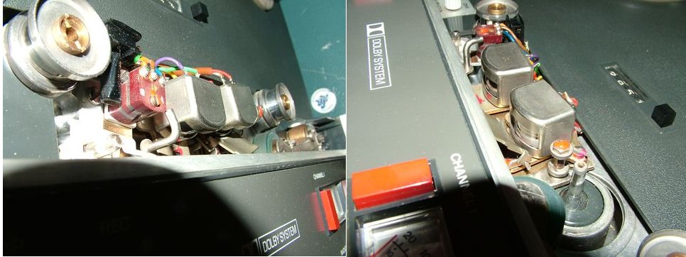
- Carefully demagnetize the heads & tape path with TEAC E-3 head demagnetizer (with plastic insulating tape wrapped around the metallic end of the "wand" to safeguard the heads against accidental contact).
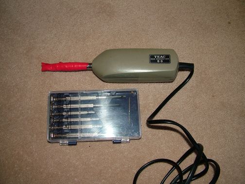
- Switch the machine off.
- Carry it to somewhere far from tapes, disks, computers, credit cards ...
- Plug in the TEAC E-3 and turn it on.
- Slowly approach the heads from 1 meter.
- Very slowly wave the TEAC E-3 around the heads, tape guides, etc.
- Very slowly withdraw to a range of > 1.5 meters while still waving E-3 slowly from left to right.
- How do you know this has worked? You don't - in the absence of a magnetic flux meter of some kind. But it very likely has!
- While the E-3 is around, use it to try to demagnetize a set of jewellers screwdrivers that we will use to adjust the head azimuth later.
- Put the A77 on some pillows, front down.
- Remove the screws at the back attaching the wooden case.
- Pull out the remote control plug at the top.
- Pull off the wooden case.
- Install a home made "bypass device" in the mains interlock mechanism. This interlock stops mains reaching the machine with the case off, and must be disabled for servicing.
- Install home made "feet" to make the thing stand off the bench. These are just 6mm thick bits of cork cut from a wine cork with holes for the case screws in the middle.
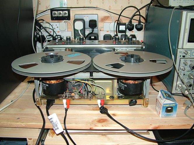
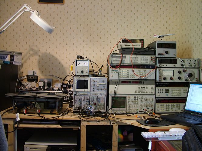
Take to the bench, where we have ...
- Tek 7834 scope. This has an amplified vertical signal output at the back, which turns out to be handy.
- HP 1740A scope, which is very easy to use in X-Y mode.
- HP 3325A synthesiser / function generator. The sine waves have <0.05% distortion, and this is fine for most audio work.
- HP 8903E distortion analyser. This is perfect for measuring AC RMS voltages in the audio range (20-100kHz with optional 80kHz or 30kHz low pass), as well as automatic distortion measurement.
- HP 3582A spectrum analyser (near DC to 25kHz, FFT based). This is a wonderful instrument, with probably the world's earliest 16 bit microprocessor at its heart.
- HP 3457A multimeter.
- HP 3400A true RMS AC voltmeter.
- HP 5370B universal time interval counter, locked to a Z3801A GPS disciplined reference oscillator. Not exactly pushed to its limits here.
The order of things from here is determined mostly by the SM section (hidden near the very end) "Alignment Instructions Revox A77 Dolby", which has 25 steps. This doesn't quite cover everything in as much detail as you would like (it is only 2 pages). We'll refer to this as "SMAID".
- Yellow +21 on PSU
- Green GND on PSU
- Measure with x1 probe on 3457A DMM
-> Read: 21.5V
- Adjust P106 on PSU
-> Read: 20.0V +/- 0.01V
- Check ripple on 7834
-> Read: < 40 mV.
This isn't in the Electrical Adjustments and Measurements part (Section 6) of the SM.
But ended up just measuring it!
See SM 6.2.2.
- Attach a x10 scope probe to tacho pickup E1 blue, E2 brown on the speed control board. Plugin in to 7A26 on 7834 scope. Set 5mV (50mV) per div. Verify that we see > 10mV (100mV) signal, which means the tacho pickup position is OK.
- Plug 7834 vertical signal out (on back panel) to 5370B channel 2 / freq. input. This amplifies the 15mV signal (after division by the probe) to a level the counter can use.
- Measure the frequency. It should be 1600Hz for 7.5ips, 800 Hz for 3.75 ips.
-> Read: 1596 Hz at 7.5 ips, 801 Hz at 3.75 ips.
- Adjust the core of discriminator transformer T201 to change 7.5ips speed (this thing seems to be a sort of resonant circuit that you tune to get the speed control). BUT ... there is NO WAY that you can adjust this in situ! AND if you try, there is a high probability of touching 150 VAC that feeds the capstan motor! This hurts ... The only way to do this would be to take the speed control board out of the machine and leave it "hanging" on its connections while adjusting. This reqires the removal of 3 screws attaching it to the transformer. These are fiddly to get at and could easily drop in to the machine. I chickened out! So, it is running 0.3% slow at 7.5ips and 0.1% fast at 3.75ips ...
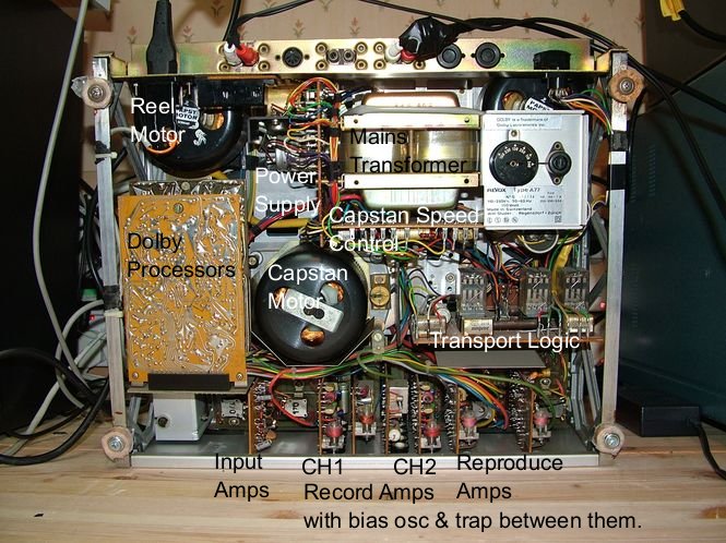
Location of the usual (non Dolby) alignment adjustments.
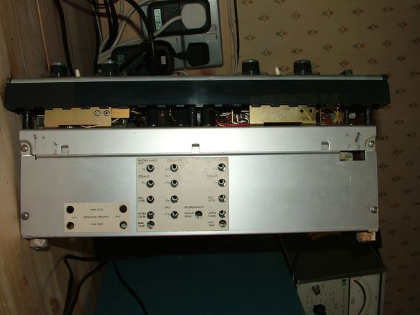
- Attach a x10 scope probe to first the orange wire, then the brown, on the erase head, with probe ground clip to chassis.
- Attach probe to 3457A DMM and 7834 scope in parallel.
- Attach 7834 scope vertical out to 5370B counter freq. input.
-> Bias oscillator freq was 123.4 kHz (141 Hz SD). Nominal 120 kHz +/- 5%, so OK.
-> Voltage at Orange: 27.0Vrms (32V nominal on 4 track).
-> Voltage at Brown: 13.7Vrms (16V nominal).
- Set both RECORD LEVELs to ZERO.
- Set both CHANNEL RECORD SWITCHES to ON.
- Set OUTPUT to full.
- Set CHANNELS to STEREO.
- Set MONITOR to INPUT.
- Load tape and start to RECORD.
- Attach x1 probe to CH1 record amplifier with probe on C517 lead as per SM diagram.
- Attach probe ground clip to adjacent coil L501 metal body.
- Plug probe in to 3457A DMM and 7A26 on 7834 scope. Take 7834 vert out to 5370B freq input.
- Adjust L501 coil slug for a minimum voltage.
-> Min obtainable was 323 mV (Goal is < 300 mV). Not ideal.
- Repeat for CH2 (pretty much identical results).
- Attach x1 probe to top of P801 (contact farthest from coil) on CH1 reproduce amp.
- Attach probe ground clip to coil L801 metal body.
- Plug probe in to 3400A VTVM.
- Set 3400A to 10mV range.
- Adjust L801 coil slug to get a minimum reading on 3400A.
-> 2mV (Goal < 50mV). This is suspiciously low ... but may be good!
- NOTE: This is NOT the procedure given in ANY of the manuals. SMAID and SM/JM disagree on the procedure. SM says to look at the output RCAs, SMAID says look at the P801 wiper - but does not say where to set the wiper. I used what I thought was a more sensible variant of SMAID. It is probably wrong, and either SMAID or SM/JM should be followed. JM hints it really doesn't matter much.
This is where the real fun began! Some careful preparation was undertaken to try to make sense of where to measure the many things that needed to be measured. Unfortunately, when making pretty much the first adjustment (to P102), this trimpot literally fell apart! So, there was a pause while the record and playback processors had all their trimpots replaced! This was not so simple. I couldn't find the right size of trimpots at either RadioSpares or Maplin ... Maybe I didn't try hard enough. But a lot of components had recently become "no longer available" due to RoHS compliance requirements... The substitute trimpots were Piher enclosed verticals, and seem to be fine - albeit needing small wire jumpers to attach the legs at either side to the PCBs. Not ideal ... but it seems satisfactory.
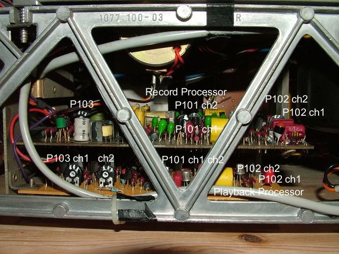
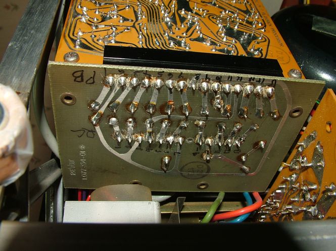
To make the required measurements, I found it necessary to tack solder leads from the measuring instruments to the appropriate "pins" on the edge connectors on the "DOLBY Basic Board" (1.077.854).
- Stop RECORDing.
- Remove tape.
- Starting with Channel 1:
- Attach a "BNC to wires" coax test lead to "P1" (pin 2) with ground to pin 6. This is used to measure AC voltages.
- Plug this test lead in to 3400A VTVM or 3457A DMM.
- Plug 3325A Generator in to AUX inputs with a "BNC to dual RCA with 50ohm termination" test lead. This lets the accurately calibrated 3325A amplitude settings appear at the RCA plugs.
- Set front panel RECORD LEVEL to full.
- Set DOLBY switch OUT.
- Set trimpots P101 and P102 for CH1 fully anti-clockwise.
- Set 3325A frequency to 5kHz and adjust amplitude to get 3mV on 3400A/3457A. This required 0.45mV.
- Transfer test lead to "P3" (pin 1). 3400A should now read 2.6mV. It did.
- Set DOLBY switch IN.
- There should be a +8dB (x2.51) increase (to 7mV approx). There was.
- Adjust P102 (CH1) to get a +10dB (x3.16) increase on 2.6mV which is 8.2mV.
- Adjust P101 (CH1) to get a -2dB (x0.795) reduction, which is 6.51mV.
- Repeat with CH2 ... same again, but with these connection changes:
- Attach a "BNC to wires" coax test lead to "P2" (pin 12) with ground to pin 6.
- to g) Repeat these steps for CH2.
- Transfer test lead to "P4" (pin 13). 3400A should now read 2.6mV.
- to l) Repeat these steps for CH2.
Unfortunately, I noticed that CH2 needed 0.59mV to get the measured 3mV ... indicating a problem with the input amplifier. This fitted with the fact that the CH2 RECORD LEVEL had always had to be set considerably higher than CH1 to get equal levels on the meters and by hearing... More later on this.
These "line up" the Playback Processor to undo the modifcations the Record Processor makes to the signal. So ...
- Starting with Channel 1:
- Set P102 (CH1) and P101 (CH1) fully anti-clockwise.
- Set DOLBY switch OUT.
- Attach FIRST "BNC to wires" coax test lead to "P6" (pin 9) with ground to pin 10. This is used to inject a signal from the 3325A.
- Attach SECOND "BNC to wires" coax test lead to "P8" (pin 1), also with ground to pin 10 (or pin 6 on Record Processor if easier). This is used to measure AC voltages and is attached to the 3400A or 3457A.
- Adjust 3325A amplitude (at 5kHZ) until 3400A/3457A measures 7.6 mV. Start at about 0.4mV and adjust. It required 3.25mV.
- Set DOLBY switch IN.
- Adjust P102 to reduce the voltage on "P7" by -10dB (x0.316) to get 2.4 mV.
- Adjust P101 to increase the voltage by +2dB (x1.259) to get 3mV.
- Repeat with CH2 ... but with these connection changes:
- Attach FIRST (input) lead to "P5" (pin 13).
- Attach SECOND (output) lead to "P7" (pin 15).
This is done on the DOLBY Playback Processor board in the DOLBY A77. The "usual" adjustments on the Record Amplifiers do nothing.
- Starting with Channel 1:
- Attach a "BNC to wires" coax test lead to "P1" (pin 2) with ground to pin 6 on the Playback Processor edge connector. This is used to measure AC voltages.
- Plug this test lead in to 3400A VTVM or 3457A DMM.
- Plug 3325A Generator in to AUX inputs with a "BNC to dual RCA with 50ohm termination" test lead. This lets the accurately calibrated 3325A amplitude settings appear at the RCA plugs.
- Set front panel RECORD LEVEL to full.
- Set DOLBY switch OUT.
- Set 3325A to 1kHz frequency and about 13mV amplitude.
- Adjust 3325A amplitude to get 100mV measured at "P1" on 3400A/3457A.
- Adjust P103 (CH1) on Playback Processor until CH1 VU meter reads 0VU.
- Repeat with CH2 ... with one connection change:
- Attach measurement lead to "P2" (pin 12)
- Sadly, the probable input amplifier problem could not be ignored at this point. Leaving the 3325A at 15.4 mV gave only 64mV measured at "P2" ... Something was wrong! Also, the CH1 distortion measured under the above conditions (1kHz, input amplitude adjusted to get 100mV at P1/P2) was 0.09% on CH1 and >2% on CH2! Ugh!
There was nothing obviously wrong with the Input Amplifier module, so I started taking out and testing first the electrolytic capacitors, then the tantalums, then all the other passives ... Nothing changed. I then swapped the two PNP transistors over (CH1 -> CH2, etc.). Nothing changed ... which was just as well, as I had no spares. Then I changed all the NPN transistors ... to BC548B's ... and it worked! I did also clean the edge connector with an eraser at the same time. So ... who knows which one fixed it? It seems unlikely that all 4 NPNs were bad - although I had previously changed one in the working channel (CH1) about 5 years ago. That time it was definitely the transistor that fixed a problem with horrendous distortion.
This is simply the Balance Control.
- Set both RECORD LEVELs to full.
- Set both CHANNEL RECORD SWITCHES to ON.
- Set OUTPUT to full.
- Set MONITOR to INPUT.
- Attach 3325A to Aux input, feeding the output simultaneously to both channels.
- Set amplitude to 30mV and frequency to 1kHz.
- With inputs disconnected, superimpose traces on 7834 scope.
- Feed output CH1 to 7A26 / 7843 scope CH1 input with direct lead.
- And CH2 output to 7A26 CH2 input.
- Set gain to same on both 7A26 inputs.
- Adjust Balance until the traces are superimposed.
- Use Sellotape to fix Balance control in place while still being able to adjust Tape/Input/Cal switch.
This is where we adjust the "tilt" of the playback head wrt the tape.
- Set both CHANNEL RECORD SWITCHES to OFF.
- Set both RECORD LEVELs to ZERO.
- Set CHANNELS to STEREO.
- Load Ernst Schmid's 7.5 ips AZIMUTH ALIGNMENT TAPE.
- Attach CH1 OUTPUT to HP 1740A scope CH1 INPUT and to 3400A VTVM.
- Attach CH2 OUTPUT to 1740A CH2 INPUT.
- Select X-Y MODE on 1740A.
- PLAY TAPE, using the 10kHz section.
- Adjust SCREW C on PLAYBACK HEAD MOUNT to change azimuth with demagnetized screwdriver.
- Try to get a maximum on 3400A. (This should be done on MONO in theory.)
- Observe Lissajous figure on 1740A. Ideally, aim for a line at 45 degrees. A complete mess would indicate a false azimuth maximum.
- Move the TAPE to the "4 TONE" section.
- Attach output to 3582A Spectrum Analyzer.
- Set 3582A to 25kHz full span.
- Set CHANNELS to MONO.
- Observe near equal amplitude of four tones at 1kHz, 4.5kHz, 7.25kHz and 12kHz. (Frequencies are approximate).
We now set the REPRODUCE LEVELS on the REPRODUCE AMPLIFIERS to get the correct output for a given magnetization on the tape.
Using a precorded tape with various tones on it, we observe the playback frequency response.
| Freq. | CH1 mV | CH2 mV |
| 10Hz | 138 | 139 |
| 40Hz | 300 | 240 |
| 125Hz | 210 | 190 |
| 500Hz | 174 | 165 |
| 1kHz | 154 | 147 |
| 4kHz | 139 | 137 |
| 8kHz | 135 | 137 |
| 12.5kHz | 134 | 137 |
| 16kHz | 132 | 137 |
| 18kHz | 135 | 135 |
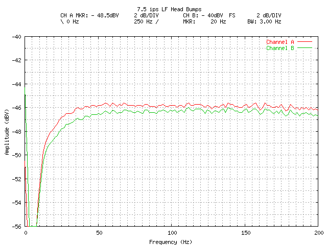
Note the low frequency "hump" starting below 1kHz. This is almost certainly normal, and is a result of the test tape having been recorded with 1 full width track. When this is reproduced on a multi-track machine, "fringing effects" known to occur below 1kHz will cause low frequency "bumps", expected to be several dB up (and down) at the bottom end.
Now we have got the playback side of things sorted out, we can usefully start on the record side!
- Set both CHANNEL RECORD SWITCHES to ON.
- Set both RECORD LEVELs to FULL (clockwise).
- Set CHANNELS to STEREO.
- Set OUTPUT to FULL.
- Set MONITOR to INPUT.
- Attach 8903E to CH1 output, measuring AC LEVEL, RMS mode.
- Plug 3325A Generator in to AUX inputs with a "BNC to dual RCA with 50ohm termination" test lead. This lets the accurately calibrated 3325A amplitude settings appear at the RCA plugs.
- Set 3325A to 1kHz frequency.
- Adjust 3325A amplitude until 8903E measures 200mV. This required 2.48 mV. This should be -20dB on the VU meters. It was.
Now we need to pass the signal through the record-reproduce path:
- Load a scratch tape.
- Set MONITOR to tape.
- Set 3325A to 10kHz output frequency.
- Start RECORDing...
- Slowly adjust the record head azimuth adjustment screw (B in the manual) looking for a maximum reading on the 8903E (or 3400A ... an analog display is quite useful for this.
The infamous "setting up the bias level for the tape" ... There is a setting of the bias amplitude that will give the best combination of noise floor, distortion and frequency response. This is a compromise - no one bias setting will optimize all three simultaneously! We start at the lowest bias amplitude. Recordings made at this level will tend to sound "bright" and very noticeably distorted. Pretty horrible. As the bias is increased, the high frequency response will first increase (get even "brighter"). Continuing to increase the bias amplitude, the high frequency response will start to fall off, and the distortion and noise will also start to decrease. The "amplitude peak" as the bias amplitude is increased can be seen on a voltmeter. The "best" bias level for a given tape brand is specified as a desired decrease in output relative to the level at the amplitude peak. This desired decrease is tape speed dependent ...
In practice, the "peak" may be very close to the level obtained with minimum bias amplitude, so it can be quite hard to see. But using the level at minimum bias isn't going to be far off under those circumstances.
For a given tape and tape speed, we look up the "best" bias decrease in a table supplied by Revox (SM Table 6.5-69 amended for more modern tapes in the "Supplement to the Adjustment Instructions (Chapter 6)").
For Ampex 456 tape, at 7.5 ips, -6dB (x 0.5) and at 3.75 ips, it is -5dB (x 0.56). With other "modern tapes" (e.g. BASF / EMTEC / RMGI 468) the correct bias settings will be very close to the Ampex 456 levels - or so I believe.
- Setup as above for Record Head Azimuth Adjustment.
- Run the tape at 7.5 ips
- Set CH1 7.5IPS OSCILLATOR to MINIMUM (fully ccw).
- Slowly increase until a PEAK is observed on the 3400A or 8903E.
- Note the PEAK LEVEL.
- Multiply this by the -6dB scale factor (x 0.5).
- Continue to increase CH1 7.5IPS OSCILLATOR until PEAK LEVEL x 0.5 is achieved.
- The bias level for CH1 at 7.5 ips is now set to its optimum level.
- Repeat for CH2 at 7.5 ips.
- Then for CH1 and CH2 at 3.75 ips (using -5dB, x 0.56 scale factor).
The PEAK LEVEL measurements (in Volts) we actually made doing this were:
| 7.5 ips | Peak | Want |
| CH1 | 0.43 | 0.215 |
| CH2 |
0.40 |
0.200 |
| 3.75 ips | Peak | Want |
| CH1 | 0.36 | 0.201 |
| CH2 | 0.46 | 0.260 |
Now the good thing is that I can honestly say that these settings also sounded best ... from a quick listen, anyway. The difference between input and recorded output was now very slight.
This procedure is specific to the Dolby version and isn't all that clearly described in any manual. We need to adjust the VU meters in RECORD so that they read the correct level.
- Set RECORD LEVEL controls to FULL (clock wise).
- Set DOLBY OUT.
- Set DOLBY RECORD CAL POTS to MIN (fully counter-clockwise).
- Set MONITOR to INPUT.
- Apply 3325A to AUX INPUTs.
- Set 3325A FREQ to 1kHz.
- Set 3325A AMPLITUDE so that VU meters read -1dB. This required 13.5 mV rms.
Now, we start to record and monitor what comes off tape.
- Set MONITOR to TAPE.
- Start to RECORD.
- Increase 3325A AMPLITUDE by +10dB (to 42.7 mV).
- Adjust RECORD AMPLIFIER RECORD LEVEL control (P503) until VU meter reads 0dB.
- Set 3325A AMPLITUDE back by -10dB to 13.5 mV.
- Verify VU meters read -10dB.
Now set the DOLBY RECORD CAL POTS ...
- Adjust DOLBY RECORD CAL POTS clockwise, until ...
- VU meters read 0dB
Now we can set the Calibration Oscillator level correctly.
- Close the RECORD LEVEL pots, so there is no input signal present.
- Switch MONITOR to CAL, so the input is from the calibration oscillator.
- Adjust CAL OSCILLATOR LEVEL using P103 on DOLBY Record Processor until VU meters read 0dB again.
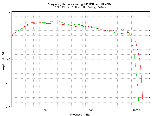
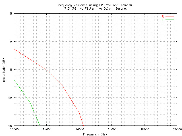
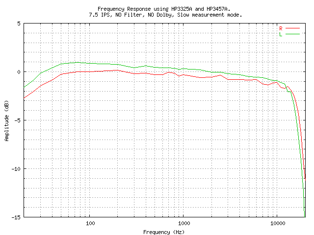
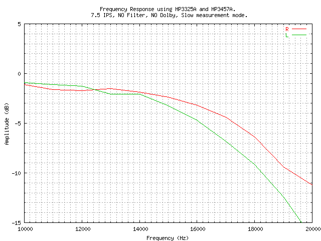
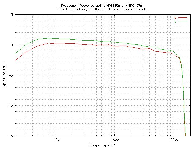
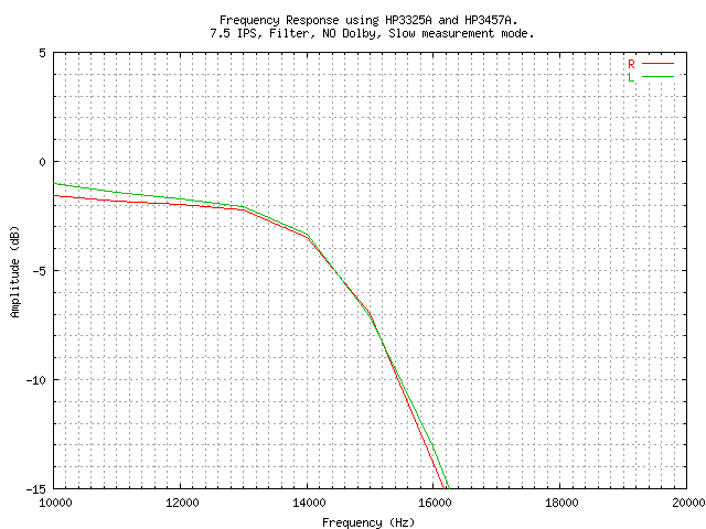
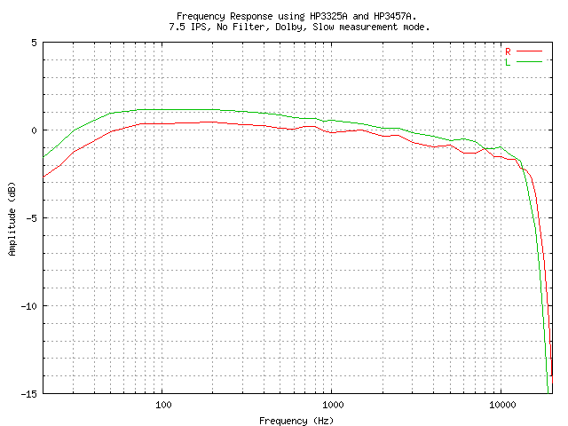
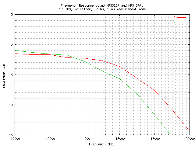
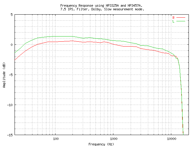
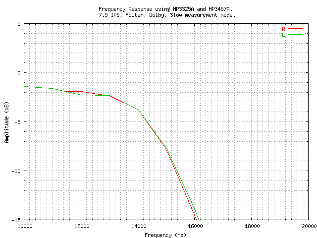
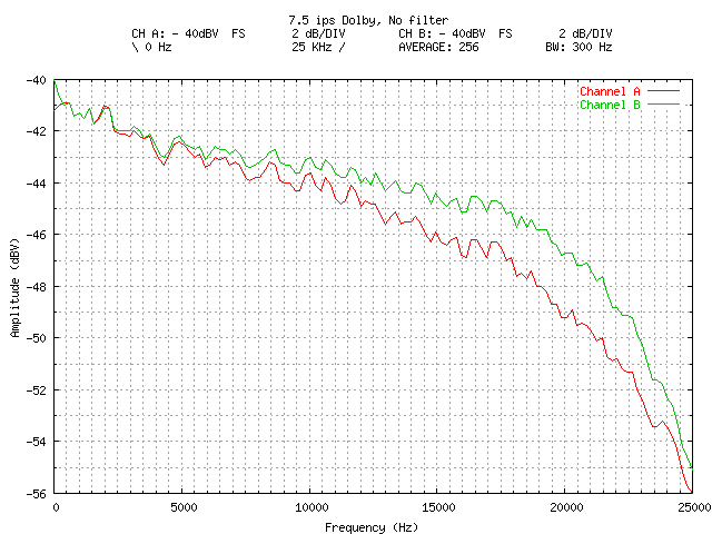
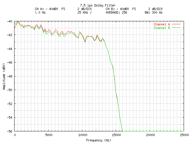
Well, yes! It certainly sounds a great deal better now - in fact it IS (finally) as good as I had always hoped it would be. It is quite difficult to hear any difference between "input" and "off-tape" now (there is hiss in quiet passages, of course, but you don't really notice it).
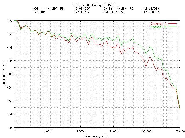
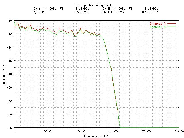
How about some measurements? Here are some frequency response charts. These were made with the HP3325A as a source and the HP3457A as the measuring device, under GPIB control. The graphs were drawn from the automatically measured data using GNUPLOT. These were taken with the record level adjusted to 0VU
